

We are your ONE-STOP solution to all your mechanical engineering needs!
Our team of master’s degree mechanical engineers has designed complete power-trains, tubular chassis, independent suspensions, fuel delivery systems, cooling ducting, turbochargers and so on.
Over the past 6 years in the mechanical engineering business, our team has received certified training from PTC, ANSYS, Windchill, REDHAT, etc. That training does not come cheap. However, we have realized that it is essential , to deliver to our clients expert know-how and understanding of the subject matter at hand. We have been blessed to have developed unique skills in modeling surfaces and solids alike.
Give us coordinates or dimensions, we can make ends meet!

We have modeled and designed over 600 GB worth of DATA. What does that mean? Well, very simply put, a complete internal combustion engine assembly has on average max. 2.5 GB. So, to put things
into perspective, we have done the equivalent of 100 internal combustion engine assemblies.
Having done everything from basic conceptual product layout to its design optimization, we have the skills necessary to propel your products ahead.
CAE is a big standard in the industry. Meshing and refining mesh, needless to say meshing negative volumes, is not everybody’s strong suit. We can proudly say, that we are ahead of the game in
this area of expertise. Setting up contact, target, mobile and reference surfaces along with contacts and joints of large assemblies is no easy task, especially knowing which one is which. Others
might have trouble, but we don’t.
Let us put your products on track!
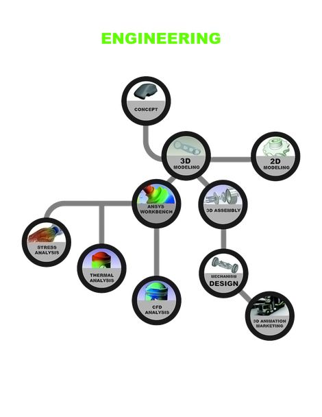
Our engineering workflow:
File Formats:
We handle projects that range from concepts to product enhancements. Our Pro-Engineer Wildfire-4, Wildfire-5, Creo-1 and Creo-2 Software gives us the ability to handle native PRO-E files with a .prt extension dating back to 2007. This gives us the ability to use pre-existing PRO-E files, since the .prt extension is not downstream compatible. Wildfire-5 files will not open in Wildfire-4! We not only use .prt files, but also .stp, .igs, .stl, etc., to make use of your existing CAD files. Certainly, we have used .pdf files to model parts from prints.
Our seats of PRO-E Enterprise SE include CAD 3-D Modeling, 2-D Drafting, Assembly, Mechanism Design, Piping, etc.
Design Layout / Animation:
We pre-render concepts using 3-D Studio Max, a non-parametric software. These renders can be edited for marketing purposes and conceptual design layouts.
Computer Aided Engineering (CAD) -Modeling:
Once a design layout is selected, a mechanical engineer makes use of PRO-E, a parametric CAD modeler, to model the part or assembly. Once the part or sub-assembly is modeled it can potentially be introduced into another larger assembly.
CAD Mechanism Design:
Upon assembling multiple assemblies, the engineer can test the kinematic mechanism’s functionality. Meaning he/she can attach virtual servos, springs, gears, etc. to test the full range of motion of the assembly. This plays a vital role in determining, if multiple parts (bodies), sub-assemblies have a collision in the mechanism (interference).
CAE (Computer Aided Engineering) Analysis:
Upon completing the mechanism design stage, the engineer takes the part, sub-assembly or larger assembly into Ansys Workbench to mesh the assembly’s 3-D parts or to mesh the assembly’s 3-D negative volume surrounding the parts geometry. The first is used for structural, thermal, modal, fatigue, etc. analysis, while the later is used for CFD (Computational Fluid Dynamic) analysis.
Upon evaluation of the results, the engineer consults with the client and the pre-defined SOW to see if the requirements are met. Should the y requirements have not been met, the engineer goes downstream in the process to update or alter the 3-D geometry of the part or assemblies involved and begins the workflow once again from that stage.
CAD 2-D Drafting:
In the case of having met the requirements, the engineer goes back to the CAD utility, in our case Pro-E, to draft the 2-D Drawings with Geometrical and Dimensional Tolerances, which are necessary for the manufacturing of the same.
Data Storage:
After sign-off on a project, the clients data gets stored on our in-house in excess of 25 TB storage servers with Tape Back-Up. The CAD DATA
-3D Models- get stored in an Oracle Database Management solution by Pro-Engineer- Windchill.
High Performance Computing:
To handle large CAE analysis files, which can take up to multiple weeks to complete, we make use of Supermicro Superserver blade systems which run RedHat Enterprise OS. All of our workstations are equipped with 4.0 GHz Quad-Core water cooled cpus, with min. 12 GB of RAM.
The largest single servers have 32 cores and 96 GB of RAM
We engineer perfection!